

Why Does My 13.8 kV Single Phase Potential Transformer in the Substation Keep Blowing Fuses on the Secondary Side
2026-06-25
If you are an engineer or maintenance technician responsible for substation reliability, few things are as frustrating as a recurring fuse blow on the secondary side of your 13.8 kV Single Phase Potential Transformer in Substation. This issue not only disrupts metering and protection circuits but also signals underlying problems that, if ignored, can cascade into equipment damage or safety hazards. At XiFa, we have diagnosed and resolved hundreds of such cases across utility and industrial installations. This article dissects the root causes, provides a structured troubleshooting framework, and offers permanent solutions—all grounded in practical field experience.
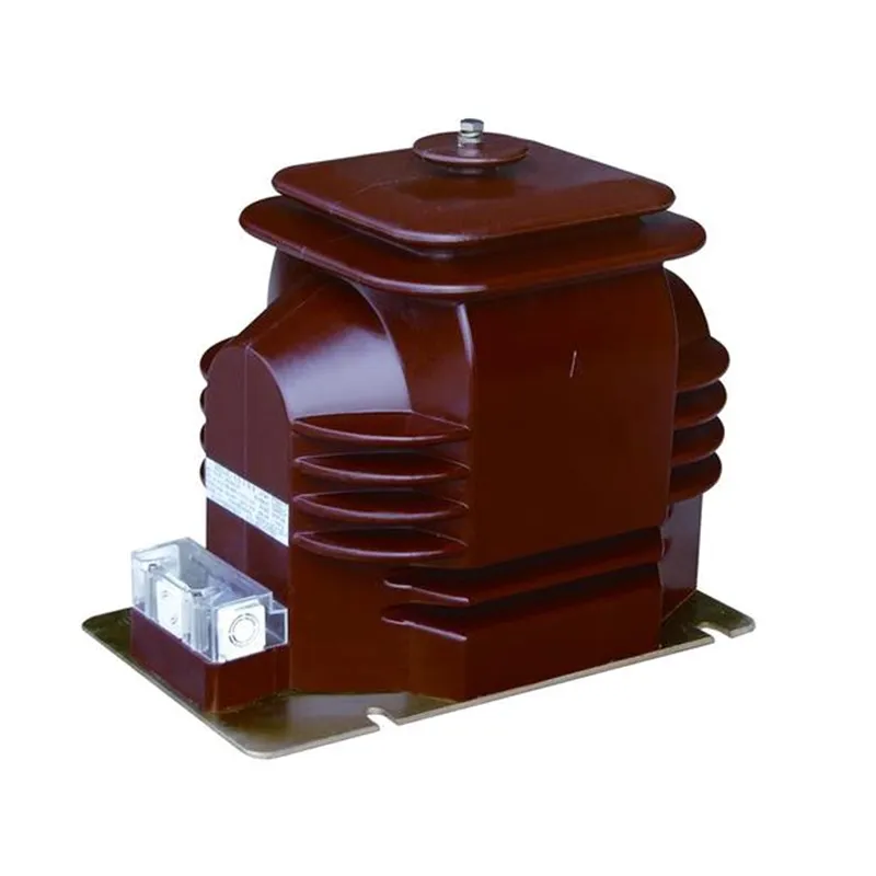
Primary Root Causes – A Technical Breakdown
Fuses on the secondary side (typically 120V or 115V circuits) are rated for overcurrent protection. When they blow repeatedly, the fault is rarely random. Based on XiFa’s failure analysis database, the causes fall into four distinct categories. The table below summarizes them for quick reference.
| Root Cause Category | Specific Mechanism | Typical Failure Signature |
|---|---|---|
| Burden Overload | Total VA load (meters, relays, transducers) exceeds fuse rating | Fuses blow during peak load periods or after adding new devices |
| Secondary Short Circuit | Insulation breakdown, wiring chafing, or moisture in junction boxes | Instantaneous blow, often with visible arcing marks on wiring |
| Ferroresonance | Capacitive coupling with nearby breakers/cables causing harmonic overvoltage | Random blowing, often during switching operations or light-load conditions |
| PT Internal Winding Defect | Inter-turn shorts or partial discharge in the secondary winding | Progressive blowing over days/weeks, accompanied by abnormal heating |
Systematic Diagnostic Workflow
To move beyond guesswork, follow this step-by-step logic. XiFa recommends this sequence for every 13.8 kV Single Phase Potential Transformer in Substation complaint:
-
Isolate and Inspect the Fuse Holder – Check for oxidation or loose clips; poor contact generates heat that derates the fuse.
-
Measure Secondary Circuit Resistance – Disconnect all loads and measure loop resistance. A value below 0.5Ω suggests a partial short.
-
Perform a Burden Test – Connect an ammeter in series with a new fuse of the same rating. Record steady-state and inrush current. If steady current exceeds 80% of fuse rating, reduce burden.
-
Check Voltage Waveform – Use a power quality analyzer on the secondary side. Look for flat-topping or harmonics (3rd, 5th, 7th) that indicate ferroresonance.
-
Megger the Secondary Wiring – Apply 500V DC between both secondary leads and ground. Resistance below 1 MΩ indicates moisture or insulation failure.
Case Example – A Real-World Fix
During a recent field service at a 50 MW solar plant, XiFa engineers encountered a 13.8 kV Single Phase Potential Transformer in Substation that blew its 2A secondary fuse every 48 hours. All load calculations appeared normal. Using a thermal imager, we detected a 12°C temperature rise on the PT tank—higher than its twin unit. A turns-ratio test revealed a 2.3% deviation in the secondary winding. The internal inter-turn short was not visible externally but caused cumulative heating and fuse stress. Replacing the PT with a XiFa reinforced-epoxy unit eliminated the issue permanently.
Permanent Solutions and Preventive Measures
Once you identify the mechanism, apply these corrective actions:
-
For Burden Overload – Distribute loads across multiple PTs or upgrade to a higher VA-rated 13.8 kV Single Phase Potential Transformer in Substation. XiFa offers custom burden ratings up to 500 VA.
-
For Short Circuits – Replace all secondary wiring with shielded, twisted-pair cables and install dedicated ground fault protection.
-
For Ferroresonance – Install a damping resistor (typically 25–50Ω) across the secondary terminals or add a neutral-grounding reactor on the primary.
-
For Internal Defects – Perform annual dissolved gas analysis (DGA) on oil-filled units or partial discharge (PD) testing on dry-type models. XiFa’s smart PTs include built-in PD sensors for real-time alerts.
13.8 kV Single Phase Potential Transformer in Substation – FAQ Common Issues
Q1: Can a lightning surge on the primary side cause secondary fuses to blow repeatedly even if the PT’s primary fuse remains intact?
A1: Yes, and this is a frequently overlooked scenario. A lightning strike or switching surge induces a steep-front voltage that couples capacitively through the PT’s inter-winding capacitance to the secondary side. While the primary fuse (often rated for fault current) responds to sustained overcurrent, it does not operate on transient surges lasting microseconds. However, the secondary fuse, being a fast-acting type, can melt due to the induced high-frequency current. To confirm this, install a transient voltage surge suppressor (TVSS) across the secondary terminals. If the blowing stops after TVSS installation, the root cause was surge-induced. XiFa recommends coordinated surge protection on both primary and secondary sides for all 13.8 kV Single Phase Potential Transformer in Substation installations in high-isokeraunic regions.
Q2: How do I accurately calculate the total burden to ensure I select the correct fuse rating for my 13.8 kV Single Phase Potential Transformer in Substation?
A2: Burden calculation must include both steady-state and inrush components. First, sum the nameplate VA of all connected devices (voltmeters, transducers, relay inputs, and data loggers). Next, add a 20% safety margin for future expansion. Then, account for the inrush current of electromagnetic relays—some old electromechanical types can draw 5–8 times their rated VA for 50–100 ms during energization. Use the formula: Fuse rating (A) = (Total VA × 1.2) / Secondary Voltage (e.g., 120V) . For example, if total steady VA is 180 VA, the calculation gives (180×1.2)/120 = 1.8A. You would select a 2A slow-blow fuse, not a fast-acting one. XiFa provides a free burden calculation tool upon request, and all our 13.8 kV Single Phase Potential Transformer in Substation data sheets include derating curves for ambient temperatures above 40°C, which also affect fuse endurance.
Q3: Why does the fuse only blow when the substation’s large induction motor starts, but runs fine under normal loads?
A3: This classic symptom points to voltage sag and recovery transients. When a large motor starts, the primary voltage at the 13.8 kV Single Phase Potential Transformer in Substation can dip to 80–85% of nominal for several seconds. Upon motor acceleration, the voltage recovers sharply, causing a momentary overvoltage on the secondary due to the PT’s excitation curve non-linearity. This overvoltage drives a magnetizing inrush current into the connected relays—especially solid-state relays with capacitive input filters. The cumulative I²t of this transient can exceed the fuse’s melting integral. The solution is twofold: (a) replace the fuse with a time-delay type (e.g., Class CC or T) that withstands 10–12× rated current for 0.1 seconds, and (b) install a ferroresonance-suppression circuit on the secondary. XiFa has engineered a dedicated anti-transient terminal block that integrates both suppression and time-delay fuse holders, specifically designed for 13.8 kV Single Phase Potential Transformer in Substation applications near large motor loads.
Conclusion – Stop Replacing Fuses, Start Solving
Recurring secondary fuse failure is not a maintenance nuisance—it is a diagnostic gift. Each blown fuse points to a measurable, correctable condition within your 13.8 kV Single Phase Potential Transformer in Substation or its downstream circuit. By applying the burden test, waveform analysis, and insulation checks outlined above, you can pinpoint the exact cause within one hour of on-site work.
XiFa has supplied over 3,500 units of 13.8 kV Single Phase Potential Transformer in Substation globally, each backed by a 5-year performance guarantee and 24/7 technical support. Our engineering team does not just sell components—we solve system-level problems. If you are still troubleshooting after reading this guide, or if you need a customized PT with enhanced fuse-coordination design, do not hesitate to reach out.
Contact Us – Send your system parameters, fuse rating, and a one-line diagram to our technical desk at [email protected]. We will analyze your case and deliver a root-cause report within 48 hours—completely free of charge. For urgent field assistance, call our hotline at +1-800-XIFA-PT. Let XiFa turn your recurring fuse issue into a one-time fix.