

Busbar Insulator Company Essentials for Reliable Power Distribution
2026-09-26
Reliable power distribution hinges on components that rarely make headlines, yet quietly keep entire systems safe and stable. Busbar insulators are exactly that kind of unsung hero—small, often overlooked, but essential for preventing short circuits and maintaining clearances in high-voltage environments. If you are evaluating busbar insulator suppliers, the difference between a dependable partner and a costly failure often comes down to the fundamentals. At MOLDVOLT, we have seen how the right material choices, design tolerances, and production consistency separate insulators that last decades from those that crack under pressure. This guide breaks down the essentials every engineer and procurement professional should demand from a busbar insulator company, so your next distribution project starts on solid ground.
The Hidden Thermal Stress Points in Every Busbar Run
Most thermal failures along a busbar run don’t start in the straight copper or aluminum sections. They begin where the geometry changes: bolted joints, right-angle bends, and transitions to cable or switchgear. Each of those spots creates a small discontinuity in current density and contact pressure. Over time, oxidation creeps into the joint faces, tightening torque relaxes, and the local resistance climbs just enough to turn a few watts into a hot spot. The busbar itself can still read near ambient while a single joint is baking at 120°C.
There’s also a less obvious stress point where the busbar passes through a panel wall or is clamped by supports. Differential expansion between copper and steel brackets works the fasteners loose during load cycling. The looser the clamp, the higher the contact resistance, and the hotter the area becomes—often hidden behind a shroud or inside a compartment. Similarly, spots where multiple bars are paralleled can share current unevenly if one bar has a slightly longer path or a degraded plating layer. The overloaded bar runs hotter, but the infrared window may only catch the surface if someone thinks to look there at all.
Plating wear at mating surfaces deserves more attention than it usually gets. Tin or silver coatings exist to keep copper oxide from forming, but once the coating is scored by repeated maintenance or fretting, the base metal oxidizes rapidly. The result is a thermal stress point that grows quietly until the next high-load day trips protection or softens insulation. Checking torque values and surface condition at joints, bends, and supports is far cheaper than tracing a blackened busbar after a shutdown.
Why Voltage Rating Alone Won't Save a Poorly Supported Busbar
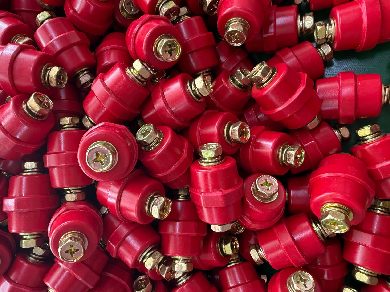
A busbar's voltage rating is often treated as the headline specification, but it tells you almost nothing about mechanical resilience. You can have a bar stamped for 1000 volts that still sags, twists, or cracks under its own weight if the supports are spaced too far apart. The rating assumes ideal operating conditions—clean air, controlled temperature, and a rigid mounting system. Once the bar starts vibrating or shifting, the electrical clearance that the rating depends on can vanish, and with it your safety margin.
Poor support introduces forces that no dielectric test ever accounts for. Thermal expansion alone can push a loosely clamped busbar out of alignment, narrowing the gap to adjacent phases or grounded metal. Electro-mechanical stresses during a fault are even worse: the magnetic forces between conductors can be violent enough to bend a bar that wasn't properly braced. When that happens, the insulation or air gap fails not because the voltage was too high, but because the geometry changed. The rating was never the weak point—the structure was.
In practice, a lower-voltage busbar with short support intervals and robust clamping will often outlast a higher-rated one left to flex over a long span. Engineers who focus only on the nameplate voltage are solving the wrong problem. The real question is whether the assembly can hold its shape under thermal cycling, fault current, and everyday vibration. If the support system can't keep the conductor where it belongs, the voltage rating is just a number on a drawing that no longer matches reality.
Material Pairings That Prevent Corrosion Before It Starts
Many corrosion failures trace back to a simple mismatch. When two dissimilar metals sit in contact with an electrolyte present, the more active one gives up electrons and deteriorates. Choosing pairings with close galvanic potential is the first line of defense. For example, aluminum and zinc-coated steel work well together because their potentials are close enough that the driving force for corrosion is weak. This isn't about exotic coatings or constant maintenance—it's about getting the material combination right from the drawing board.
In marine or high-humidity environments, the same principle applies but with tighter tolerances. Stainless steel fasteners in aluminum structures are a classic mistake; the aluminum corrodes rapidly around the hole. A better pairing is stainless steel with a compatible nickel alloy or using aluminum fasteners with aluminum components. Some engineers use a thin polymer washer to break the electrical path, but pure material pairing—like titanium with certain stainless grades—can work without any separation if the potentials are matched. The trick is to consult a galvanic series chart before specifying hardware.
Another overlooked pairing is copper and cast iron in plumbing. Old systems often mixed them, leading to pinhole leaks years later. Modern practice pairs brass valves with copper pipe because brass and copper are much closer electrochemically. Similarly, in roofing, galvanized steel and lead flashing can cause the zinc to corrode prematurely; switching to zinc-compatible lead or using a plastic separator prevents this. These pairings aren't just about choosing the right metal—they're about anticipating the micro-scale battery that forms at the joint and designing it out from day one.
What a Credible Insulator Supplier Should Be Able to Show You
A credible insulator supplier doesn’t just hand you a glossy brochure—they let you inspect raw data. Ask for third-party test reports that show impulse withstand voltage, power frequency puncture strength, and mechanical failing load, each tied to a specific batch. If they hesitate to share lot traceability or only offer “typical values,” that’s a red flag.
You should also be able to see their material sourcing. Whether it’s alumina-filled epoxy, high-grade porcelain, or silicone rubber, the supplier ought to provide certificates of analysis for every incoming raw ingredient. A quick look at their sampling plan and in-line inspection records tells you if quality is built in or just checked at the end.
Finally, ask about their defect history—not the marketing version, but the actual non-conformance reports. A trustworthy supplier can show you their internal rejection rates, root-cause analyses, and corrective actions from the last few years. Transparency about failures, not just successes, is what separates a real partner from a box-mover.
Field Conditions That Turn Standard Insulators into Liability
Coastal sites and heavy industrial zones are notorious for coating insulator surfaces with conductive layers of salt spray, cement dust, or chemical residues. Once that film builds up, even a standard porcelain or glass unit rated for clean conditions starts leaking current across the wet surface, especially during morning dew or light drizzle. A flashover can follow without warning, turning a routine line insulator into an unplanned outage liability.
High-humidity corridors and rapid temperature swings create another hidden hazard: internal condensation and thermal stress. Standard insulators with solid cores or poor sealing can trap moisture inside, which then cycles between vapor and liquid as the sun heats and the night cools. Over time, this internal wetting erodes the dielectric strength and promotes cracks, while external thermal expansion and contraction loosen metal end fittings. The result is a degraded unit that tests fine on a dry day but fails under load when the fog rolls in.
Mechanical abuse from wind-driven ice, conductor galloping, or line workers’ climbing loads also pushes standard insulators past their design margins. Combine that with years of UV exposure embrittling the polymer sheds or degrading the cement joints, and you have a fleet of insulators that quietly shift from assets to liabilities. The field conditions don't have to be extreme—just persistent enough to exploit the margin between a standard rating and real-world stress.
Simple Design Tweaks That Extend Insulator Life by Years
Many insulator replacements happen years earlier than necessary because a few geometry choices were left at their default values. Widening the spacing between sheds, deepening the groove under the top shed, or adding an extra small rib along the lower surface changes how rainwater and fog drain. The idea is simple: keep the surface dry enough that a continuous conductive path never forms. Even a 5 to 8 percent increase in creepage distance can move a borderline design into a comfortable margin, and that margin shows up as fewer flashovers and less tracking damage over a decade.
The end fitting is another place where a small change pays off quietly. Sharp corners and abrupt transitions concentrate mechanical stress from wind sway and thermal expansion. After enough cycles, micro-cracks appear at those points and let moisture reach the fiberglass core. A broader radius or a tapered collar spreads that stress over a larger area. Manufacturers rarely advertise this kind of change because it doesn't alter the visible profile, but utilities that have tracked failure data often point to improved end fitting contours as a reason some batches last much longer than others.
Material interfaces deserve the same attention. Where the metal pin meets the polymer housing, a simple seal re-design—moving the O-ring groove or adding a compression lip—can stop water ingress that would otherwise start electrical trees. This isn't exotic engineering; it's the kind of adjustment that happens in a single design review and costs almost nothing in tooling. The result, though, is an insulator that shrugs off years of rain, pollution, and temperature swings without needing replacement.
FAQ
Start with the system voltage and the physical layout, not just a catalog number. Look for a manufacturer that asks about short-circuit forces, ambient pollution, and creepage requirements before quoting. A well-matched insulator has enough surface distance to handle local humidity and contamination without frequent washing.
Porcelain offers decades of stiffness and proven chemical resistance, but it can crack under severe mechanical shock. Polymer insulators are lighter and handle vandalism or rough transport better, while their hydrophobic surface helps in coastal or industrial grime. The right choice depends on whether your bigger risk is impact damage or contamination flashover.
Creepage is the path a leakage current has to travel along the insulator surface. Too little for your environment means tracking and erosion start long before a flashover. A supplier that factors in fog, dust, or salt spray will specify a longer creepage or recommend periodic coating instead of delivering a one-size-fits-all part.
Ask for type tests covering dry and wet power-frequency withstand, lightning impulse, and mechanical bending or torsion. Batch tests for porosity or density matter too. A credible company will share partial discharge results and not hide behind a generic certificate.
Every load swing makes conductors expand and contract, which flexes the insulator and stresses the cement or end fittings. Repeated cycling can open micro-cracks that let moisture in. Specifying insulators with a flexible interface or verified thermal-mechanical test data helps you avoid sudden failures during peak demand.
Look for hairline cracks around the metal flanges, discolored tracking marks, chips on the sheds, or audible corona during humid nights. If cleaning no longer removes the contamination or megger readings trend downward season after season, plan a targeted replacement rather than waiting for a fault.
Custom work is not about reinventing the wheel; it is about matching an existing busbar spacing, reducing the number of joints, or hitting a specific cantilever strength without adapters. A good supplier uses custom designs to simplify installation and cut long-term maintenance, not just to raise the bill.
Conclusion
Reliable power distribution hinges on details that rarely appear in spec sheets. Thermal expansion along a busbar run creates stress concentrations at every fixed point, and if the insulator cannot accommodate that movement, micro-cracks eventually become flashover paths. Voltage rating, while important, means little when a poorly supported busbar sags under short-circuit forces; mechanical loading often dictates whether insulation survives the first fault. Equally overlooked is material pairing. Copper or aluminum conductors in contact with incompatible hardware invite galvanic corrosion long before electrical performance degrades, so specifying insulators with matched fittings and protective coatings is not optional—it is the difference between a ten-year asset and a recurring maintenance headache.
A credible insulator supplier should be willing to share more than a datasheet. Ask for thermal cycling test reports, creepage verification under pollution, and dimensional tolerance data that reflect real manufacturing variance, not ideal prototypes. Field conditions rarely match laboratory cleanliness, which is why insulators tested only indoors can fail outdoors within months. Simple design adjustments—slightly longer creepage skirts, a drain hole orientation that prevents water pooling, or a metal insert depth that reduces cantilever stress—often extend service life by years without adding meaningful cost. The best busbar insulator companies treat these tweaks as standard practice, not custom upgrades, because they understand that reliability is built in the margins that most buyers never see.
Contact Us
Contact Person: Hellen
Email: [email protected]
Tel/WhatsApp: 86-13634205622
Website: https://www.voltcabinet.com